Mitsubishi Eclipse 3G Club banner

NC[Spyder]GT's FI Install Thread

20K views 118 replies 18 participants last post by  thahnic1080  
#1 · (Edited)
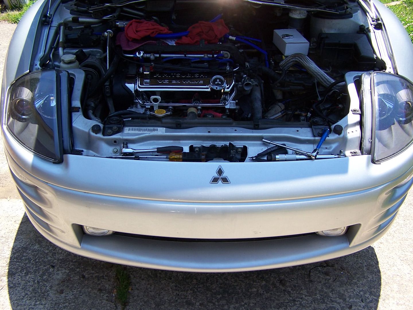
I'm in the process of installing a Ripp SDS system (blow-thru) in my car (2001/GT/5pd/Spyder/80K miles) and figured this would be a good place for me to track what I've done so far and issues I have run into. I am planning to boost as high as possible without upgrading the pistons yet. I have everything needed for Stage 3 but seeing this is my 1st FI install I will start off stage 1. Once I get a built 6G74 installed I will go to Stage 3 on that.

So far I have completed the following:
-oil pan tapped
-alt bolt direction reversed
-Greddy oil block adapter installed
-310cc venom injectors installed
-radiator bracket cut/hacked
-compression test done and all is well
-windshield wiper fluid resevoir removed (no squirters so not needed)
-SDS idler pulley bolted to AC bracket bracket and torqued
-machined upper alt bracket installed

(edit updates:)
-oil lines & fittings installed
-oil psi probe/gauge installed
-radiator hose prepped
-coolant neck shortened for upper hose

Some quick questions to keep me moving forward:
1) Does the upper coolant hose "nipple" really have to have 1.25" cut off of it? We are talking about where the OEM upper radiator hose connects, right?
2) Any idea what the torque spec is for the SDS idler pulley bolt (connects Ripp pulley to the aluminum Ripp bracket near the alt)?
3) Does the Black box have to be sent in (or retuned) anytime you change engine parts or change Stages of the SDS system?
4) Is it possible to run Stage 2 without upgraded pistons and using the Meth pump? I guess I am not sure what makes it "Stage 2".
5) Does the crank pulley need to be replaced with the one from Ripp for Stage 1? For Stage 2?

Thanks in advance!
 
#6 ·
Will do! And guys don't think I am being lazy! I WILL call Ripp ASAP to get questioned answered. Just wanted to check here 1st as I trust this community's responses more than Ripp's (plus I am at work ATM). I will try and get pics as I proceed.

I'd love to see some photos of how others have their oil lines routed. I know the drain line will go between the heater hose and the AC compressor but I'm not sure about the feed line. Based off of Ripp's install photos I'm guessing that one is routed between the block and the front header tubes? I'm leary of just running it like that without knowing how others did it. I'd plan to secure it but I can just imagine the hose touching the headers and melting :lol: hence my eason for wanting a photo!

BTW, I will supply +rep as I am able!!! Many thanks for the feedback guys!
 
#8 ·
1) Does the upper coolant hose "nipple" really have to have 1.25" cut off of it? We are talking about where the OEM upper radiator hose connects, right?
Yes, you have to do it. It is not hard and your can use a hack saw while the outlet is on the car. No removal needed. Just put a cloth inside the outlet to prevent metal fragments from getting down to the thermostat.

2) Any idea what the torque spec is for the SDS idler pulley bolt (connects Ripp pulley to the aluminum Ripp bracket near the alt)?
No more than 25-28 lbs. or you'll strip the thing. Put on Locktite on the bolt first.

3) Does the Black box have to be sent in (or retuned) anytime you change engine parts or change Stages of the SDS system?
At one time, yes. They now have provide some tuning software for the BB. So you can adjust the tune a bit.

4) Is it possible to run Stage 2 without upgraded pistons and using the Meth pump? I guess I am not sure what makes it "Stage 2".
Yes you can. BUT... 1)you better have control of your tune. 2)you need to understand that you have little room for error with the stock pistons. 3) you may need more than the BB to control that tune.

5) Does the crank pulley need to be replaced with the one from Ripp for Stage 1? For Stage 2?
The standard kit that comes from Ripp is the Stage 1. The Stage 1 has larger pulley (~2 7/8") than Stage 2 (~2.5" ...the exact dimensions I can't remember). You don't need the crank pulley. But if you add it, you get significantly higher boost levels with both SDS pulleys. Some where in this forum, someone laid out the psi level for each pulley setup... I've been drinking, so I can't remember. :drunk: :chug:
 
#9 ·
The standard kit that comes from Ripp is the Stage 1. The Stage 1 has larger pulley (~2 7/8") than Stage 2 (~2.5" ...the exact dimensions I can't remember). You don't need the crank pulley. But if you add it, you get significantly higher boost levels with both SDS pulleys. Some where in this forum, someone laid out the psi level for each pulley setup... I've been drinking, so I can't remember. :drunk: :chug:
Im pretty sure the crank pulley added 2 psi.
 
#10 ·
Stage I - Large Shaft Pulley, Stock Crank Pulley 5-8psi
Stage II - Small Shaft Pulley, Stock Crank Pulley 8-13psi
Stage II.5 - Large Shaft Pulley, Aluminum Overdrive Crank Pulley 14-16 psi
Stage III - Small Shaft Pulley, Aluminum Overdrive Crank Pulley 17-20+psi

All of the Psi range will depend on your whole setup, by that I mean how much back pressure your car has, how much air flow it has through the intake, TB, Manifolds, Heads, Cams, Port and Polish, ect..
 
#12 · (Edited)
Can anyone tell me how to release/remove the OEM high pressure fuel line to hardline fitting? I'm not seeing any real info in the FSM about this and I have searched extensively! Maybe I don't have the proper sized wrenches?? We tried soaking it in Liquid Wrench but that had no effect. Maybe heat with a torch and try again?! LOL, j/k!
Image


I assume the breaker bar (3/4" head) is rotated counter-clockwise/left and the smaller (14mm) wrench is kept in place or rotated clockwise/right? Do you have to push in on the fuel line while doing this or anything? I'm going to wait for suggestions then I'll try my last resort idea of cutting the hardline itself and reflaring it (37deg) for an AN fitting. I'd REALLY like to avoid that though as I hear sometimes if the hardline is too hard/strong that the flaring tool just pops off the line/tube without creating a flare. And if that happened I'd be looking at a tow to a shop (and back) plus their labor charges :( I can't imagine how much a shop would charge to mess with a hardline like this :dunno:

:help: (again) ;)

:edit: Just got back from Autozone and I saw they have a bunch of tools called "fuel fitting quick disconnects". Are one of those needed? I'd have no idea how to use it. No directions were included.
 
#13 ·
Why do you need to pull that fuel line off? Does the fitting not work for your fuel rail? Anyhow, I meant lbs/ft. for the idler pulley.
 
#14 ·
Why do you need to pull that fuel line off? Does the fitting not work for your fuel rail?
I am currently using the OEM fuel rail fittings for my VR4 rails :angryazn: Fugly @ best. The A1000 FPR I got is completely polished. Because of this I picked up some SS lines to use with it (why have fugly lines going to something nice?) I need to get an AN fitting onto the hardline in order to use it with the A1000. I think everyone using the A1000 is using AN fittings :dunno: Last time I checked I think I was the only one not able to remove the fitting which maked me think I am missing something! :scratch:
I need to search some more I guess as its been awhile since I last reviewed this... gave up after repeated failures :noplease: BUT I'm back at it now! :ndance:

Anyhow, I meant lbs/ft. for the idler pulley.
:worship: I'm on it! Got red threadlock gel an hour ago.

I've tried repping everyone in here but I need to spread more 1st! :squint: weak but understandable.
 
#16 ·
I'm going to do that if I am unable to remove the stock fitting before this w/e. Tired of this BS! When you did your cutting did you disconnect the hardline "holder" from the firewall or did you just bend the high pressure line so you could get the cutter all the way around it? Just looking for tips I guess. Thx for the feedback! +repped.
 
#17 ·
Hey NC[spyder]GT, If you have the pipe from RIPP (the one that the BOV came on) will you measure the length of it for me, I got a piece of 2.75" aluminum pipe to weld my new BOV on and need to know how long that pipe needs to be, since I sold my last one with the BOV!
 
#18 · (Edited)
will measure it tonight

*edit* 5 13/16"
 
#20 ·
As far as the boxes, I put mine up under the dash on the passenger side of the ECU. I didn't want the clutter in the engine bay and I wanted to keep all the wiring central in one location.

Be prepared to be sore - soldering wires on your back/stomach is never fun. Pull the passenger seat (obviously) to give yourself room to spread out.
 
#21 ·
Thx for the feedback! Removing the seat may seem like a good idea to most but @ 6'8" it isn't going to help me much ;) I'm planning to put my Ripp electros right by the ECU or just to the left (maybe stuck up behind the AC channel area (under/behind glovebox). The area under/behind my cubby and stereo bezel are already too packed with other electonics so heat &/or EMI could be an issue if put there).

I'm gonna look like such dork doing the soldering... flashlight visor on, kneepads, etc LOL. Oh well, I'm pretty proficient with soldering/wiring so I'm sure it won't take long. I should have pics of the finished wiring posted this w/e. I finished all my oil lines yesterday so I'll post pics of that as well. Picking up some larger clamps for my Krankvents now so I should have them done as well by then (using silicon hosing and it is thicker than normal vac hosing so original KV clamps don't fit :angryazn:) If anyone wants any specific pics (not previously mentioned) just let me know before the w/e.

The BIG news of the day is my desperately needed polishing supplies are arriving today :woot: I bet by this w/e my valve cover, manifold, TB, strut bar, sds, piping, etc are all shiny enough to eat off of :yum: Can't wait to put that new benchtop buffer to work! :hbang:
 
#27 ·
Zeitronix EGT probe :yesway:

Any idea what size you have your injectors scaled to? I have to check how far I've gone down but last I logged I was still getting -24 for LTFT low/high/mid :( I could use a good starting # if you dont mind! You are not using the supplementals either, correct? And that is 13psi of boost and not fuel psi, right? Just gotta make sure... a lot of this is new to me :ugh:
 
#28 ·
Well, I got my valve cover installed over the w/e and the ripp piping polished. Also got my upper radiator hose trimmed a bit better and protected wit SS sleeving. I'll be polishing the SDS shaft and my upper manifold this week while I wait for my colder range NGK plugs to arrive.
Image


Didn't get a chance to finish the electronics, fuel, or the meth injection (wrong resevoirs sent :angryazn:) :( I'll blame that on the wifey and her last minute demands to have 8 knock-out rose bushes planted by me.

I finally found out what the metal tab was for that sticks off of the black/grey box. It is for mounting a heatsink. Apparently a heatsink is recommended when the SFS piping/injectors are used. I guess powering those 2 injectors makes enough heat to warrant cooling the black/grey box. I'm not planning to use the SFS but I do think I will feel the box after running for an hour or so. If it is warm/hot then I will go ahead and strap a heatsink to it.
 
#30 ·
You were asking about Stage 2 on stock pistons with a meth cooler previously.

I was just at RIPP this past weekend and asked both Angelo and Perry the same question. They basically said that if you do so, you're doing so at your own risk, and that if you exceed 5,000 rpm, you're likely to break your ringlands.

So as for me, after hearing that, with my stock pistons I'm staying Stage 1.
 
#31 · (Edited)
Many thanks! I'll use the normal shaft pulley and the stock crank pulley with no meth for now. I'll probably add meth after a few weeks but stick with the stage1 pulleys. Looks like I will be getting a built 3.5L soon and I'll end up going Stage 3 with that.

Thanks for the comments on the look of the engine bay. She still has a long way to go (IMO) but things should start coming together this week when the polished manifold, TB, Ripp piping, and SDS are mounted. I'm hoping to wrap a few plastic pieces with silver CF as well but that will probably take me a month or two as I will be learning on the fly.

I have ordered a new cone filter, black box tuning cable/software, and spark plugs from Ripp and they should arrive by this w/e. Things seem to be moving forward well with the install :)
 
#32 ·
Yeh, couple years ago my stock motor didnt last very long on stage 2 + meth injection. My car was seeing around 15psi on stage 2 on the stock motor. I'd say it lasted 10 pulls.
 
#40 ·
The 310cc injectors came from Ripp so they are not "outside the box". They used those before the SFS, IIRC.
 
#43 ·
:naughty: Thx! I almost regret installing it... last night I went to install my NGK sparks and sat there staring at the VC for like 10mins. Felt like a moth near a light bulb LOL.

I now have the SDS shaft aligned and bolted to the block. I have installed the BB software as well. It looks like Ripp provided a tune for a 4G on the CD-ROM and maybe one for a 3G :dunno: I'll have to call and see exactly how I load that. I will say that for $60 this "burned" (copied) CD almost seems pirated :ugh: There is a security/key feature built into the software but the instructions tell you how to get by that. There do seem to be TONS of settings but I don't think it seems TOO over the top. Hopefully I can find and load a baseline file/ROM/tune and then tweak from there. I definately do NOT have the skills (yet LOL) to config this thing from scratch! I also note that the cable could be made at Radio Shack (or similar) for like $5. I'll be pinning it out a making a diagram for future reference.

I have ordered a new coolant resevoir and meth tank. I'm hoping to have all the electronics, piping, and MAP/boost probes done early next week. If all goes well then I'll have her fired up by nex w/e. More pics to come.
 
#44 · (Edited)
I have installed my new longer serpentine belt and noticed that the RIPP instrctions do not show how to route the belt. Does anyone have a diagra or photos showing the proper route? I only saw one way to do it but it seemed like the belt cameVER close o touching itself between the SDS idler pulley and I believe the OEM tensioner pulley. I'd like some feedback before I proceed! I'll try to get a pic of my routing tonight. The only thing I see in the SDS instructions about the belt is this:
Shitty RIPP Instructions said:
• Install belt supplied in kit (see illustration provided with kit)
• Remove factory air flow meter harness from factory loom and gently pull out loom route over mass air

HINT: Make note of the belt size and put it in the glove box for future reference.
*They don't even provide a photo :angryazn:


Also, is there an instrucion manual for the RIPP belt tensioner? I do not see how to adjust it or how to install it onto the SDS shaft. I could get it mounted, as is, on the shaft if I had an extra set of hands but the only person available to help right now is my WEAK wife lol! Thoughts?
 
#45 ·
I have installed my new longer serpentine belt and noticed that the RIPP instrctions do not show how to route the belt. Does anyone have a diagra or photos showing the proper route? I only saw one way to do it but it seemed like the belt cameVER close o touching itself between the SDS idler pulley and I believe the OEM tensioner pulley. I'd like some feedback before I proceed! I'll try to get a pic of my routing tonight. The only thing I see in the SDS instructions about the belt is this:

*They don't even provide a photo :angryazn:


Also, is there an instrucion manual for the RIPP belt tensioner? I do not see how to adjust it or how to install it onto the SDS shaft. I could get it mounted, as is, on the shaft if I had an extra set of hands but the only person available to help right now is my WEAK wife lol! Thoughts?
First let me say, do not quote me on this picture, I did not make it, I only found it on the forums awhile back.

<a href="http://imageshack.us"><img src="http://img113.imageshack.us/img113/4102/sdsroutingrf8.gif" border="0" alt="Image Hosted by ImageShack.us"/></a><br/><a href="http://g.imageshack.us/g.php?h=113&i=sdsroutingrf8.gif"><img src="http://img113.imageshack.us/img113/4102/sdsroutingrf8.fe1d0fd20b.jpg" border="0"></a>

The tensioner is very simple, it just bolts on by the pulley, it will line up evenly with the belt. It kind of hard to explain without pictures so I will step out side and take some for you. Ill have them posted in a few minutes.
 
#46 ·
<a href="http://imageshack.us"><img src="http://img113.imageshack.us/img113/5843/003bv2.jpg" border="0" alt="Image Hosted by ImageShack.us"/></a><br/><a href="http://g.imageshack.us/g.php?h=113&i=003bv2.jpg"><img src="http://img113.imageshack.us/img113/5843/003bv2.bead3761a2.jpg" border="0"></a>

<a href="http://imageshack.us"><img src="http://img162.imageshack.us/img162/5435/004yh7.jpg" border="0" alt="Image Hosted by ImageShack.us"/></a><br/><a href="http://g.imageshack.us/g.php?h=162&i=004yh7.jpg"><img src="http://img162.imageshack.us/img162/5435/004yh7.3da73b0175.jpg" border="0"></a>

<a href="http://imageshack.us"><img src="http://img113.imageshack.us/img113/4677/005jh1.jpg" border="0" alt="Image Hosted by ImageShack.us"/></a><br/><a href="http://g.imageshack.us/g.php?h=113&i=005jh1.jpg"><img src="http://img113.imageshack.us/img113/4677/005jh1.402f3b8b32.jpg" border="0"></a>

<a href="http://imageshack.us"><img src="http://img162.imageshack.us/img162/1688/006yd5.jpg" border="0" alt="Image Hosted by ImageShack.us"/></a><br/><a href="http://g.imageshack.us/g.php?h=162&i=006yd5.jpg"><img src="http://img162.imageshack.us/img162/1688/006yd5.7db96c32b2.jpg" border="0"></a>